-
Timeline - The 1850s
Decisions made during this decade would lead to conflict to come. From a Compromise in 1850 to a Dred Scott decision that would cause a nation to increasingly become two distinct parts, it was all prompted by new territories in the westward expansion movement wanting to become states and trying to decide which part of the divide they should be or allowed to be on. There would be raids in Harpers Ferry with participants that would soon become part of the other side. There would be Presidents who just did not know what to do.
More 1800s
Timeline Book

ABH Travel Tip
Some of the most surprising locations of historical significance within the National Park Service lay in little known or less attended sites. One gem is Harper's Ferry. This town, site of not only John Brown's famous abolitionist uprising, but Civil War battles throughout the Great Rebellion, includes dozens of restored buildings, with exhibits on the topics, as well as the Appalachian Trail, Jefferson's Rock, and whitewater rafting opportunities on the Shenandoah and Potomac Rivers. Almost the entire town is restored within the park system, and access to it, outside a small parking lot, is through a Park Service shuttle bus on the bluff above town.
Sponsor this page. Your banner or text ad can fill the space above.
Click here to Sponsor the page and how to reserve your ad.
-
Timeline
Detail - 1855
October 9, 1855 - The Shuttle Sewing Machine and its machine motor are patented by Isaac M. Singer, improving the development of the sewing machine.

Isaac Merritt Singer was born in Schaghiticoke, New York, 1811, son of a German immigrant Adam, who had emigrated to the United States to become a millwright and farmer. He was raised Lutheran, his mother Ruth's faith, but endured a contentious upbringing due to his father. When Isaac left school in 1828, he surprisingly became an actor, performing in the Edwin Dean Theater Company and the Baltimore Strolling Players; neither were successful. Singer had apprenticed in a mechanics shop and understood the engineering of machines. By 1839, he had sold the patent for a rock-drilling machine for two thousand dollars. But his love of theater (picture above does seem awefully thespian) would still call. He used the profit to start the touring Merritt Players Company; they went bankrupt.
Once back in the mechanic machine trade where he belonged, he formed partnerships and got investors for various projects, both unsuccessful and successful, including a type-carving machine for printers, backed by Boston printer George Zieber and partner Orson Phelps. Singer agreed to work for them. At their shop, he was introduced to the Blodgett Leroy sewing machine, which he thought impractical.
"Instead of the shuttle going around in a circle, I would have it move to and fro in a straight line. In place of the needle bar pushing a curved needle horizontally, I would have a straight needle and make it work up and down," Isaac Singer.
As evidenced by that introduction, Isaac Singer was not on the forefront of the sewing machine invention. Elias Howe, Walter Hunt, and Charles Frederick Weisenthal had thought of the sewing machine first, but their machines were not practical enough, as with the Blodgett Leroy machine, for daily use. So Singer thought he could make modifications according to the quote above that would make the machines useful and affordable to people other than tailors. Other machines cost an average of $252 at the time, a huge sum for a homemaker. In 1850, his bosses Zieber and Phelps gave him three thousand dollars to work on making the necessary improvements. It only took him eleven days and forty dollars. By 1851, he patented a modification and started the I.M. Singer Company. In two years, sales were the highest in the nation. However, in 1855, under Patent No. 13,661, the second machine had surpassed their first, extending its functionality. It controlled slack. It added a continuous fabric feed. It provided consistent stitch spacing. The new machine that the public would buy was born. And it was durable enough for factory use. With the assistance of marketing expert and lawyer Edward Clark, the Singer Sewing Machine was inexpensive and became a necessity in many households. This patent allowed the sewing machine technology to be practical for the public.
Success After the Patent
Isaac Singer, with his theatric training, and Edward Clark, began to promote the machines voraciously. They first went to tailors, then traveled the county fair circuit to demonstrate the machine to women, by women. They began selling their invention and giving credit for their $100 to $130 dollar machines. The 1855 Paris World's Fair awarded the machine a First Prize. In 1857, they opened up their own decorated window shop at 458 Broadway, New York City, fronting their office. Clark offered half priced machines to minister's wives, thinking their use would sell it by itself to parishioners. In the early 1860's when the Civil War broke out, they provided machines, for free, to the Union Army. The firm was incorporated in 1863, holding twenty-two patents and worth $550,000, at the same time their relationship began to sour. Singer's lifestyle became a problem, but did not hinder the company. He had been notorious in his exploits with various women; first marriage to a fifteen year old, Maria Haley, then another relationship with Mary Ann Sponsler, whom he had forgetten to tell about his wife. There were more wives and mistresses. All told, it is thought he had twenty-four children. Eventually Edward Clark took over the operations of the company as Isaac Singer moved to Europe. Production after the Civil War grew quickly; sixty thousand machines per year, then over eighty thousand in the next decade. By 1873, the Singer Sewing Machine Company had three thousand employees at their plant in Elizabethport, New Jersey. The plant had over 1.8 million square feet of floor space. By 1890, they had an eighty percent share of the global sewing machines market.
Today the Singer Sewing Machine Company is a vibrant corporation one hundred and seventy-five years old in 2026. It still focuses on beginner machines for households, but has professional models, as well as embroidery and quilting machines. They have evolved into a broader company, owning the Husqvarna and Viking brands, plus accessories such as thread and needles through PFAFF. Its headquarters is now in Nashville, Tennessee, and owned by the conglomerate SVP Worldwide, which is an American owned private company. That company has affiliates and sales in one hundred and eighty countries. It remains the largest manufacture of sewing machines in the world, although its share is much lower than near its inception, selling one in three machines around the world. Revenue as of 2024 was $500 million per year. The company has around three thousand employees.

Singer Shuttle Sewing Machine Patent
IMPROVEMENT IN SEWING-MACHINES
Specification forming part of Letters Patent No. 13,661, dated October 9, 1855.
To all whom it may concern: Be it known that I, ISAAC M. SINGER, of the city, county, and State of New York, have invented certain new and useful improvements in Sewing-Machines, of which the following is a full, clear, and exact description, reference being had to the accompanying drawings, making part of this specification, in which -
Figure 1 is a plan of the table or bench of the machine with the covering of the shuttle-race removed; Fig.2, a front elevation; Fig. 3, a horizontal section taken in a plane just below the bench or table, and Fig. 4 a separate elevation of the shuttle.
The same letters indicate like parts in all the figures.
The first part of my invention, which relates to a method of controlling the shuttle-thread, is intended to overcome or avoid the difficulties arising from the shuttle-thread being loose between the cloth or other substance to be sewed and the hole in the shuttle through which it passes. From this loose condition of the shuttle-thread it often happens that the thread gets in the way of the needle, which pierces it, and when this does not happen it gets sometimes on one side and then on the other, producing unevenness in the stitches.
The first part of my invention, to avoid this defect, consists in attaching to the upper surface of the shuttle a spring thread-guide, attached at one or both ends to the shuttle and extending nearly the whole length thereof and making pressure on the thread, the rear end being curved for a short distance and then straight or in a line parallel with the line of the motion of the shuttle, so that when the shuttle advances the thread shall be drawn back under the spring and back to the curve, and when the shuttle moves back the thread shall be held by the curve of the said guide, by which it is held in a straight line until after the needle enters the cloth, and then it slips off from the curved part of the guide, preparatory to the other operations; and the second part of my invention, which relates to the feed motion for spacing the stitches, consists in giving a continuous feed motion in combination with a vibratory needle, that the needle may follow the feed motion while it remains in the substance to be sewed, and be restored to its original position by a spring or its equivalent the moment it leaves the substance, preparatory to another stitch. By irregularity in the spacing of the stitches due to the necessity of overcoming friction and the inertia of all the moving parts when operating with an intermittent feed motion, which irregularity is marked when sewing heavy articles, such as ships' sails, traces, and other parts of harness-work, etc.
In the accompanying drawings, which represent a well-known sewing-machine with my improvements added, a represents the shuttle-carrier, sliding in the shuttle race b in the bench and operated in the usual manner. Near one end of the carrier is secured the shuttle-driver c, which is simply an arm extending out from the carrier to a sufficient distance to act against the rear end of the shuttle d, to drive the shuttle through the loop of the needle-thread. There is a projection, e, on the carrier, the edge of which is beveled to correspond with the bevel of the forward end of the shuttle, and the position of this projection on the carrier relative to the shuttle-driver is such that when the shuttle is in place between them it will have sufficient end-play to allow the needle-thread to pass freely between the rear end of the shuttle and the driver when the shuttle is forced forward against the beveled edge of the projection e. The object of the projection e is not to drive back the shuttle, but simply to act as a guard to prevent the shuttle from moving forward beyond certain limits. The mode of imparting the back movement to the shuttle will be described hereinafter.
The shuttle is forced through the loop of the needle-thread by the driver acting against the rear end of the shuttle, and when the loop passes off at the rear end of the shuttle, as the machines have heretofore been made, the carrier stops and the shuttle is carried forward a short distance by the impetus, to permit the thread to escape; but as the shuttle is immediately after driven back by the other driver it often happens that the thread is caught between the end of the shuttle and the rear driver. To obviate this I put a lever, f, on the carrier, with a spur, g, projecting from it, which enters a recess in the shuttle, and the forward edge of this spur is beveled so that when this end of the lever is forced toward the shuttle the beveled face of the projection, acting against the edge or face of the recess in the shuttle, forces it (the shuttle) forward, and as this lever is connected to and moves with the carrier as well as the driver the motion thus imparted to the shuttle is in addition to any motion derived from the driver, and, in consequence, the shuttle is driven forward and clear of the driver, to permit the free passage of the thread.
The motion above described is communicated to the lever f toward the end of the forward motion of the shuttle-carrier, which bring the end h of the said lever which is beveled against a bevel surface or fixed cam, i, attached to the bed in the shuttle-race. The rear edge of the spur g, as it is forced into the recess to give the required forward motion, above described, to the shuttle, is brought into contact with the rear face of the recess in the shuttle, and is thus enabled on the return motion to perform in addition the office of shuttle-driver to carry the shuttle back to its starting-place.
To the upper surface of the shuttle I secure a spring, j, made of fine wire, the two ends of which are secured to the upper surface of the shuttle, with its under surface in such proximity to the surface of the shuttle as to permit the thread k from the shuttle as to permit the thread k from the shuttle to pass under it and press it gently onto the surface of the shuttle and yield to any inequality. From that end nearest the point of the shuttle the spring extends in the line of the length of the shuttle to within a short distance of the other or rear end, where it is curved, as at l. From under this spring the shuttle-thread passes to the cloth or other substance to be sewed, and as the shuttle moves forward the thread slides under the spring to the rear end thereof, where it is curved, and as it moves back the thread is held by the dirve l and the tension of the spring to take up the slack which otherewise would be formed, and thus keeps it (the thread) distended from the seam to the curve of the spring until the point of the needle enters the cloth, and then it slips around the curve l, to be ready for the other operations. In this way it will be seen that the shuttle-thread is always drawn in the same direction and out of the way when the point of the needle enters the cloth, so that all the stitches will have the same appearance, instead of being inclined sometimes in one direction and sometimes in another, and the thread can never be pierced by the needle.
The needle-bar m is connected with the sliding needle-carrier n by a joint-pin, o, at the upper end, so that it can vibrate in the direction of the motion of the shuttle, and it is provided with a dedicated spring, p, (represented by dotted lines if Fig. 2,) the tension of which tends constantly to carry the needle q to the extent of its range of motion in the direction the reverse of the feed motion, to be presently described.
The cloth or other substance placed on the table is pressed by the usual pressured-pad, r, down onto the periphery of the feed-wheel, s, which presses up through a mortise in the table or bench. This feed-wheel receives a continuous motion in the direction of the arrow, to move the cloth or other substance continuously by a worm, t, the thread of which engages the cogs of a worm-wheel on the shaft of the feed-wheel. The worm t is on a shaft, u, which receives motion by bevel-wheels u v from the shaft to one of a pair of concs, x x, connected by a belt, y, the other cone deriving motion from the master-wheel z by a cog-wheel, a, on its shaft U. The belt y of the pair of cones is controlled by a belt-shipper, c, on the end of a lever, d, that turns on a fulcrum-pin, d, the other arm, f, of the said lever having a hole to receive a pin, g, which can be set in any one of a series of holes in a sector, h, attached to the bench or table. As one of the cones has a positive motion corresponding with the motion of the needle and shuttle, and the belt which connects the pairs of cones can be shifted and set by the shipper at any part of the length of the cones, it follows that the motion of the feed-wheel can be increased or decreased relatively to the motion of the needle and shuttle at pleasure to lengthen or shorten the stitches. Now, as the feed motion is continuous, the moment the point of the needle enters the substance to be sewed it begins to move with the feed motin and continues to move along with it during the entire operation of forming the stitch, and until it comes out again, the needle-bar admitting of the motion by reason of its connection with the carrier, above described, by a joint-pin, and the moment the needle rises out of the substance to be sewed, it is carried back to its original position by the tension of the spring p, before described. In this way I am enabled to make the feed motion continuous, and to regulate the length of the stitches at pleasure.
It will be obvious from the foregoing that instead of the gearing described for giving the continuous feed motion equivalent means may be substituted, and that instead of moving the cloth or other sustance by a continuous motion relatively to the sewing mechanism, which remains in a fixed position, and the continuous feed motion imparted to the sewing mechanism; and it will also be obvious that the form and construction of the spring for controlling the shuttle-thread and the mechanism for clearing the rear end of the shuttle from the driver may be varied within the range of my invention by the substitution of equivalent means; and, therefore, I do not wish to be understood as limiting myself to the special construction herein specified, so long as the same ends are attained by equivalent means having substantially the like mode of operation.
I claim -
1. In combination with the shuttle, and attached thereto, the employment of a spring-pressure guide, substantially as specified, to control the shuttle-thread as the needle enters the cloth or other substance to be sewed, as set forth, and for the purpose specified.
2. The continous feed motion for spacing the stitches, substantially as specified, in combination with the vibratory motion of the needle, imparted in one direction by the feed motion and in the opposite by a spring or any equivalent therefor, substantially as and for the purpose specified.
I.M. SINGER.
Witnesses:
WM H. BISHOP
ANDREW DE LACY.
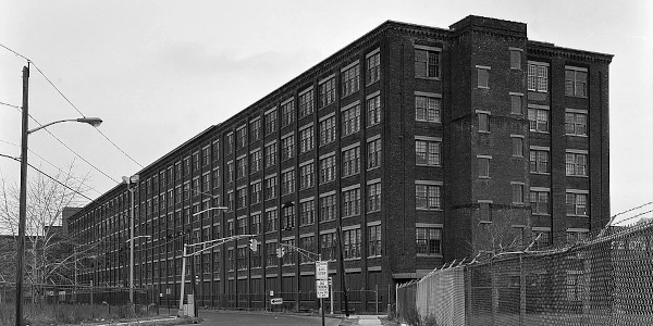
Image above: Montage (left) article in Scientific American about 1851 Isaac Merrit Singer patent, 1851, Scientific American. Courtesy Library of Congress. (right) Isaac Merrit Singer, 1869, Edward Harrison May. Courtesy Wikipedia Commons. Below: Singer Sewing Machine Company Building, constructed 1918, Elizabeth, New Jersey, Date Unknown, Historic American Buildings Survey. Courtesy Library of Congress. Info source: "M. SINGER, Sewing Machine, No. 13,661, Patented Oct. 9, 1855," Patentimages.storage.googleapis.com; "Isaac Singer Patented the Sewing Machine Motor, This Day in History," 2025, amac.us; singer.com; "What is the History of the Singer Sewing Machines Company," singermachines.co.uk; "Isaac Merritt Singer," immigrantentrepreneurship.org; svpworldwide.com; zippia.com; Wikipedia Commons.
History Photo Bomb

Fifty nations, including the United States, plus thirty-nine colonies and protectorates participate in the 1st World's Fair, The Great Exhibition of the Arts and Industries of All Nations in London's Hyde Park. This event signalled the beginning of international trade.
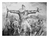
John Brown in Kansas mural. Courtesy National Archives.

Emmanuel Leutze painting, "Washington Crossing the Delaware." Courtesy National Archives.